Computer vision
MATLAB · camera calibration · image processing
Built from background subtraction and morphology to a calibrated HSV detector for six pin positions.
Final vision & integration reportA vision-guided bowling robot
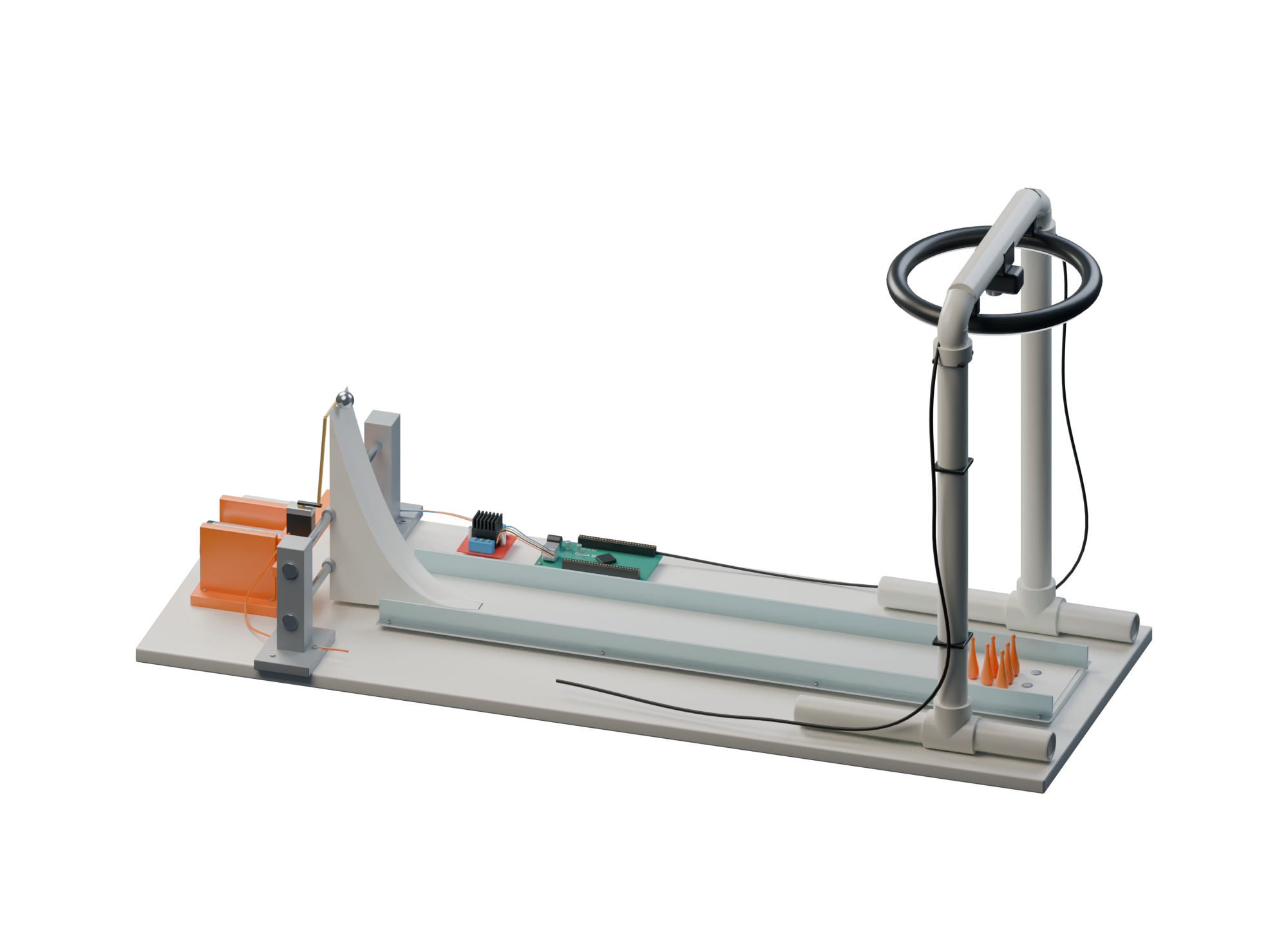
A tabletop robot that detects pins, positions a ramp and releases a steel ball.
Avi Patel · Team 19. Computer vision, encoder feedback and mechanical integration.
Camera → MATLAB → Simulink → Arduino → motion
Scroll to explore3D reconstruction from team drawings & photographs
The complete machine
A tabletop robot that detects pins, positions a ramp and releases a steel ball. Avi Patel · Team 19. Computer vision, encoder feedback and mechanical integration.
Camera → MATLAB → Simulink → Arduino → motionPosition & release
A rack and pinion slides the ramp sideways. Encoder feedback brings it to the selected position. A small servo moves the release dowel. The steel ball rolls down the V-channel and into the lane.
16-tooth gear · 8 mm guide rods · 5/8-inch steel ballCamera & calibration
The camera checks color saturation and brightness at six calibrated pin locations. A fixed camera and ring light help the software distinguish occupied positions from empty ones.
Logitech Brio · controlled lighting · calibrated pin occupancyThe team’s engineering work
Five students connected sensing, software and mechanisms to aim and release a bowling ball. The operator places the ball and pins.
MATLAB · camera calibration · image processing
Built from background subtraction and morphology to a calibrated HSV detector for six pin positions.
Final vision & integration reportSimulink · Arduino Mega · encoders · motor control
Mapped image coordinates to rack travel, tuned the position loop, and integrated motor feedback with servo release.
Controls & integration reportFusion 360 · 3D printing · rack and pinion
Combined a translating ramp, guide rods, release gate, camera fixture and containment into one working prototype.
Design drawings & assemblyDFMEA · concept comparison · staged testing
Documented design tradeoffs, compared controller responses, resolved lighting problems and evaluated the integrated build.
Development & risk analysisMATLAB/Simulink work, early camera interfacing and technical documentation within Team 19. The complete machine and demonstration are team achievements.
Explore the source evidence04 / The logic
Read the pins. Choose a target. Move the ramp. Release the ball. Then look again.
Check six calibrated positions.
Select a target manually or automatically.
Move the ramp with encoder feedback.
Open the servo gate.
Recenter and capture the remaining pins.
TRY THE TARGETING LOGIC
Toggle the pins to change the lane. The archived app scores a fixed set of expected knockdowns and picks the occupied target with the highest score.
Logic demonstration based on the archived MATLAB app. Expected knockdowns come from a lookup table; they are not a physics prediction. Ties select the first numbered target.
Under the surface
The image becomes a coordinate. The coordinate becomes a motor command. The mechanism turns it into motion.
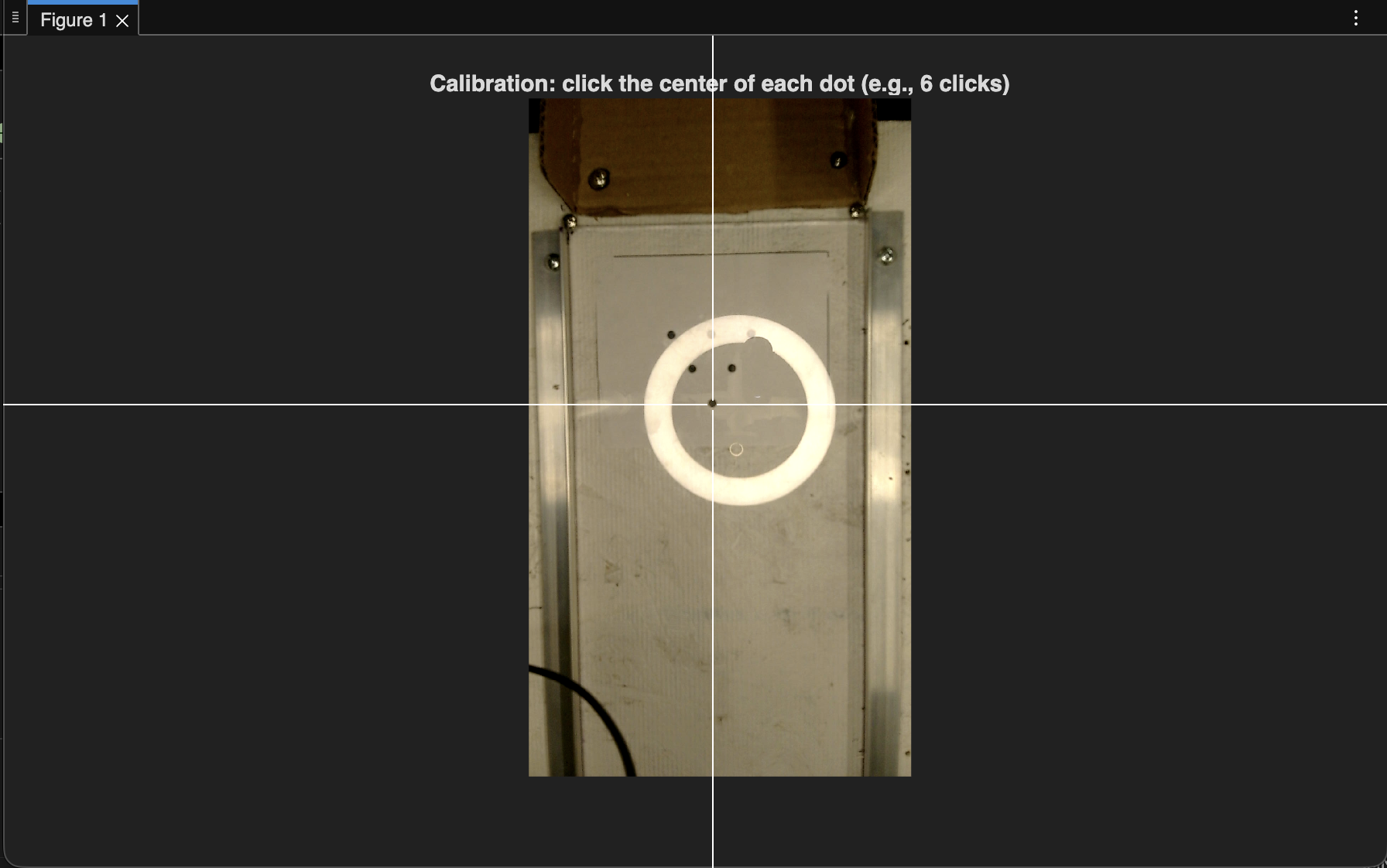
CALIBRATION → OCCUPANCY
The operator marks the lane edges and six pin dots. The app inspects a local image patch at each location, converts it to HSV, and checks mean saturation and brightness.
These are archived code settings. The final detector uses saturation and brightness at calibrated points; it does not use a trained model.
05 / The build
Four stages of iteration: from a simple signal path to a complete camera-guided machine.
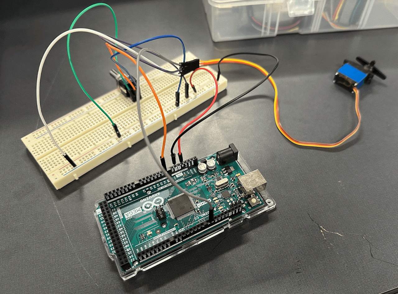
A potentiometer input commanded servo motion through MATLAB, Simulink and an Arduino. The first stage established communication, sensing and actuation before the robot took shape.
The foundation: connect a physical input to a controlled output.
Read the stage report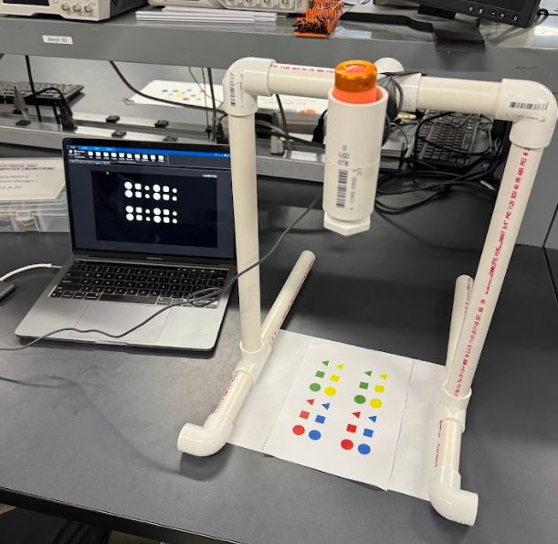
A fixed camera, PVC frame and controlled lighting supported background subtraction, morphology and color-and-shape measurements. Colored stickers made the sensing pipeline visible and testable.
Lighting and fixture stability mattered as much as the image-processing code.
Read the stage report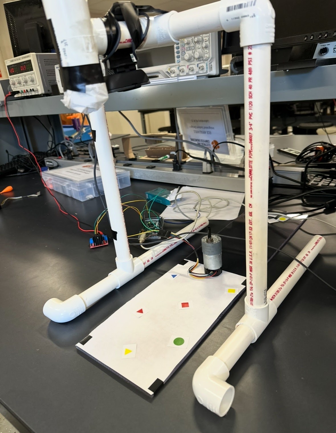
A MATLAB interface placed selectable buttons at detected object centroids. Choosing a target rotated a motor-driven pointer toward it, using encoder feedback and a tuned position controller.
Lane reflections disrupted sensing; the team used a white surface during the demonstration.
Read the stage report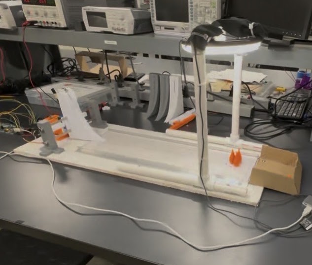
The final design replaced angular aiming with a laterally translating ramp. A servo gate, rack and pinion, ring light, rails and catch box brought the complete bowling sequence together.
Calibrated pin occupancy replaced the earlier general background-subtraction method.
Read the stage report06 / In motion
The original final demonstration: a three-pin arrangement is cleared, and the MATLAB interface updates the board.
From the team’s final presentation, slide 6.
accurate pin hits
consecutive frames
Team-reported results, without raw scored trial logs in the archive. The team reported no troubleshooting intervention during those frames; ball and pin setup remained manual. The video is one recorded sequence. Read the presentation ↗
07 / The record
Original reports, source code, drawings and footage. The engineering behind every part of the story.
Design decisions, dimensioned drawings and the integrated system.
Requirements, demonstration and team-reported results.
Archived application, motor model and development files.
Editable reconstruction, with inferred layout documented separately.
Reports and slides open as PDFs. Original editable files remain in the archive.
53 files. Four stages. The full archive.Operation. The operator places the ball and pins; the robot handles aiming, release and return. Detection depends on six calibrated locations and stable camera and lighting conditions.
Timing. The presentation reports a cycle under 10 seconds. The archived app contains 12 seconds of fixed waits before image refresh. The version and timing boundary remain unresolved.
3D reconstruction. This model uses original drawings where available and inferred layout elsewhere. The report’s illustrative 6-inch lane differs from the app’s 3.85-inch calibration setting. Read the modeling notes ↗ Download the GLB ↗
Reproducibility. These source files preserve the development record. The Simulink model references an encoder support component that is not separately included; the hardware has not been rerun here.
Clemson University / Team 19
Corey Golec · John Phillips · Jacob Criswell
Avi Patel · Josue Morales-Sanchez
A five-person ECE 4950 project, Fall 2025. Avi’s documented contributions include MATLAB/Simulink, early camera interfacing and technical documentation.
The project builds on course-provided vision code and Simulink models. Original photography, documents and footage belong to Team 19.
Original team site